Printable T S Diagram For Steam A newly developed g s state diagram for water and steam is presented in which the specific entropy s is the abscissa while pressure p and Celsius temperature t are used as parameters
In thermodynamics a temperature entropy T s diagramis a thermodynamic diagramused to visualizechanges to temperature T and specific entropy s during a thermodynamic processor cycleas the graphof a curve It is a useful and common tool particularly because it helps to visualize the heat transferduring a process Book Title T s Diagram for Water and Steam Book Subtitle IAPWS Industrial Formulation 1997 for the Thermodynamic Properties of Water and Steam Authors Hans Joachim Kretzschmar Publisher Springer Vieweg Berlin Heidelberg Copyright Information Springer Verlag Berlin Heidelberg 1998 Edition Number 1 Number of Pages 1
Printable T S Diagram For Steam
 Printable T S Diagram For Steam
https://3.bp.blogspot.com/-sT-8YzPrIYQ/TjEbi7plxdI/AAAAAAAAAJM/TR97LAqyFWM/s1600/Phase+Steam+Diagram.jpg
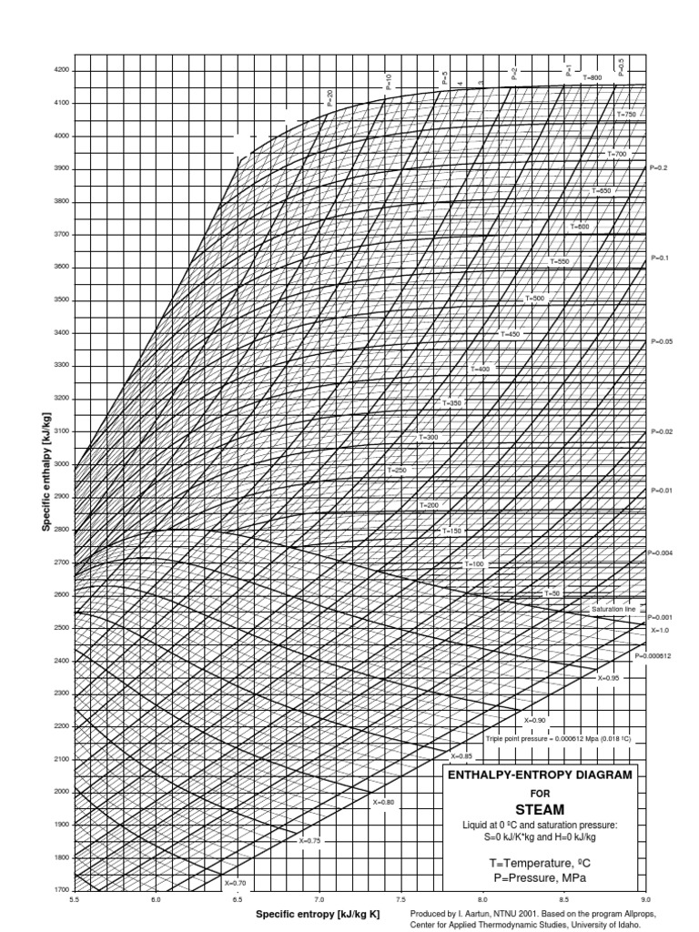
Mollier s H S diagram Enthalpy v Entropy was a logical extension of the T S diagram Temperature v Entropy first proposed by Gibbs retaining the advantages of T S diagrams but introducing several new advantages A typical H S Mollier diagram for a thermodynamic fluid such as steam is shown in Figure 1 Figure 1
Pre-crafted templates provide a time-saving option for producing a diverse variety of files and files. These pre-designed formats and designs can be used for different individual and professional tasks, including resumes, invitations, leaflets, newsletters, reports, presentations, and more, streamlining the material development process.
Printable T S Diagram For Steam

DIAGRAM Air T S Diagram MYDIAGRAM ONLINE

Printable Diagram Printable mollier diagram steam 2 Printable Mollier
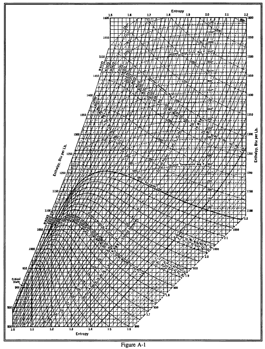
DIAGRAM T S Diagram Steam Pdf MYDIAGRAM ONLINE

Steam Turbine Circuit Diagram Wiring View And Schematics Diagram
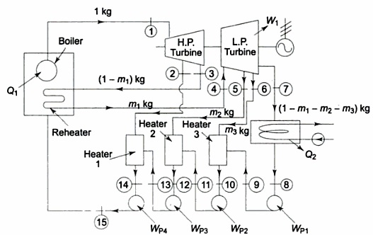
DIAGRAM Steam Power Plant Ts Diagram MYDIAGRAM ONLINE

DIAGRAM Pwr Ts Diagram MYDIAGRAM ONLINE
https://www.thermopedia.com/content/1150
S specific entropy kJ kg K t s temperature at saturation u specific internal energy kJ kg specific volume m 3 kg static dielectric constant dimensionless viscosity 10 6 kg s m MPa s thermal conductivity mW K m density kg m 3 surface tension kg s 2 N m specific entropy of vaporization kJ kg K

https://www.engineeringtoolbox.com/steam-entropy-d_99.html
The entropy diagram for steam shows the relationships between Pressure Temperature Dryness Fraction Entropy With two factors given the others can be found in the diagram The ordinates in the diagram represents the Entropy and the Absolute temperature The diagram consist of the following lines Isothermal line Pressure lines Lines of
https://engineering.wayne.edu/mechanical/pdfs/thermodynamic …
Table A 1 Molar mass gas constant and critical point properties Table A 2 Ideal gas specific heats of various common gases Table A 3 Properties of common liquids solids and foods Table A 4 Saturated water Temperature table Table A 5 Saturated water Pressure table Table A 6 Superheated water Table A 7 Compressed liquid water

https://www.engineersedge.com/thermodynamics/temp_enthalpy_th_dia…
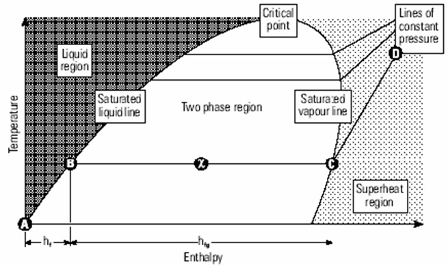
Temperature Entropy T s Diagram In the liquid vapor region in Figure 13 water and steam exist together For example at point A water with an entropy s f given by point B exists together with steam with an entropy s g given by point C

https://commons.wikimedia.org/wiki/File:T-s_diagram.svg
File T s diagram svg Size of this PNG preview of this SVG file 800 562 pixels Other resolutions 320 225 pixels 640 450 pixels 1 024 720 pixels 1 280 900 pixels 2 560 1 800 pixels 2 030 1 427 pixels
V AND T s DIAGRAMS Constant V Constant p Constant T Constant Heat s Constant V Constant s Constant p Constant T T s AND h Critical Point Figure 4 9 Outline of a temperature entropy diagram for steam From B F Dodge Chemical Engineering Thermodynamics McGraw Hill Book Co New York 1944 1650 Entropy Btu lb F 2 2 This is contrary to all current thermodynamic textbooks in which temperature entropy T s diagrams are used to represent steam power plants
The term Mollier diagram named after Richard Mollier 1863 1935 refers to any diagram that features Enthalpy on one of the coordinates Commonly used Mollier diagrams are the enthalpy entropy or h s diagram and the pressure enthalpy diagram illustrated at the bottom of this page