Printable Swr Circle Pdf We see two sets of circles on this chart the red ones represent impedance circles and the green ones represent admittance circles To read the impedance of the point shown on the Smith Chart we read the impedance circle scale and to read the admittance we read the admittance circle scales
Each circle represents a value of SWR with every point on a given circle representing the same SWR The SWR value for a given circle may be determined directly from the chart coordinate system by reading the resistance value where the SWR circle crosses the resistance axis to the right of prime center The reading where the circle crosses the We want to get from circle C1 to the center of the chart which rep resents a perfect 1 1 SWR I achieved this by extending the coax 0 30 wavelength and using a shunt capacitor of 1 200 pF Finding the 1 1 SWR Value The measured impedance is expressed as a series circuit a resistance in series with a reactance
Printable Swr Circle Pdf
 Printable Swr Circle Pdf
https://data.formsbank.com/pdf_docs_html/118/1187/118721/page_1_thumb_big.png
You can move along the constant SWR circle round and round One round is 2 360 or 2 is periodic Half a round is 180 or 4 The maximum is a quarter wavelength away from the adjacent minimum At a minimum or a maximum x d
Pre-crafted templates use a time-saving service for producing a diverse series of files and files. These pre-designed formats and designs can be made use of for various personal and expert jobs, including resumes, invitations, leaflets, newsletters, reports, discussions, and more, improving the content creation process.
Printable Swr Circle Pdf
Download 204 Circle Coloring Pages PNG PDF File Greatest Free Fonts
I Plot This In Matlab Like The Graph At The Bottom Chegg
Kraft Labels 1 0 Circle A 4 Wholesale Supplies Plus

Smith Chart Electrical Engineering Free 30 day Trial Scribd
50 Unit Circle Practice Worksheet Chessmuseum Template Library
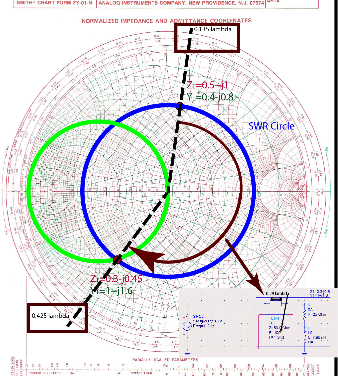
Mixed Impedance Matching Ximera
https://www.arrl.org/files/file/Antenna Book Supplemental Files/…
Fig 4 Smith Chart with SWR circles added power and with a 1 0 to 1 SWR Thus prime center also represents the 1 0 SWR circle with a radius of zero SWR circles are also discussed in a later section Short and Open Circuits On the subject of plotting impedances two special cases deserve consideration These are short circuits and open

https://www.arrl.org/files/file/Technology/tis/info/pdf/q1106037.…
SWR is a measure of what is happening to the forward and reverse voltage waveforms and how they compare in size Let s look at what happens when a trans mitter is connected to 50 coax and a 50 antenna For now pretend that the coax cable doesn t have any losses and the transmitter is producing a 1 W CW signal

https://www.nutsvolts.com/magazine/article/smith_chart_fundamentals
Figure 1 Impedance at the load The reflection coefficient L is related to the load impedance Z L and the system impedance Z o as There are resistance circles from 0 to Ohms The reactance curves on the top half of the chart are inductance curves most notable are the 0 9 and 1 0 curves at the top that curve down to the right hand center

https://eecs.wsu.edu/~shira/ee331/examples/smithcht.pdf
To find the SWR draw a circle the SWR circle centered at the origin of the r i plane through the normalized load impedance zL The SWR is the value where the circle intersects the positive real axis i e read the SWR value on the r axis

https://worldradiohistory.com//RCA-Ham-TIps/RCA-Ham-Tips …
Other SWR Circles For various cable characteristic imped ances SWR circles can be drawn by the pro cedure in the following example To draw a circle where the SWR 3 1 with a 300 ohm line the circle would 00 cut the 100 ohm point 13 100 and the 900 ohm point 300 x 3 900 on the horizontal axis The center to be used for the
Module 4 Smith Chart and S Parameters is a tutorial that introduces the basic concepts and applications of the Smith Chart and the scattering parameters in RF circuit design It covers topics such as impedance matching reflection coefficient stability circles and noise figure It is a useful resource for students and engineers who want to learn more about This article offers an introduction to the Smith chart and how it s used to make transmission line calculations and fundamental impedance matching circuits
Concentric circles around the diagram center represent constant re ection factors Fig 7 Their radius is directly proportional to the magnitude of therefore a radius of 0 5 corresponds to re ection of 3 dB half of the signal is re ected whereas the outermost circle radius 1 represents full re ection